Abstract: Intermittent signal interference in shielded cables is often not caused by a defect in the cable itself. The most common root causes are shielding grounding methods, termination processes, routing paths, connector shield bonding, and coupling from power cables. Only conditions such as broken shield braid strands, insufficient braid coverage, or damaged inner insulation truly belong to the cable body. OEMs can locate the root cause through a three-step process: on-site troubleshooting, cross-swap verification, and laboratory testing. Aichie Tech Wires provides custom single-layer and double-layer shielded cables, shielding effectiveness testing, and 7–10-day sample delivery to help solve intermittent EMC signal faults.
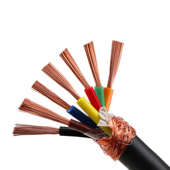
1. Intermittent Interference: Most Cases Are Not the Cable’s Fault
Intermittent interference has a typical signature: the signal is good sometimes and bad at other times. It is more likely to reappear during vibration, motor start/stop, or when high-power equipment is switched on. Many engineers immediately suspect a bad cable, but in real projects the source is usually at the system assembly level.
Wrong Shielding Grounding Scheme (Most Common)
Grounding mistakes are the number one cause of intermittent shielded-cable interference. Common problems include mixing single-point grounding with multi-point grounding, or grounding the shield at both ends and forming a ground loop. When a ground loop exists, ground potential differences generate induced noise. If vibration loosens the grounding contact, the interference appears and disappears intermittently.
Low-frequency analog signals and high-frequency communication signals cannot use the same grounding strategy. A grounding method that works for one may create serious noise for the other. Engineers must confirm the signal type, frequency range, and system grounding architecture before deciding how to terminate the shield.
Poor Shield Braid Termination
Shield braid termination is another high-frequency problem. If the braid is cut and left with loose strands, or if the shield is extended with a short “pigtail” wire, the shield’s high-frequency performance drops dramatically. Under vibration, the braid and connector shell may touch at one moment and separate at the next. The shielding effectiveness fluctuates, and the signal is intermittently disturbed.
Never use pigtail termination for high-frequency shielded cables. The pigtail introduces high inductance, which destroys the shield’s ability to drain high-frequency noise. A proper 360-degree termination is required.
Routing Layout Causes Electromagnetic Coupling
Routing is often overlooked. When shielded signal cables are bundled close to and parallel with power cables, electromagnetic coupling can occur. Servo drives, inverters, and other high-current cables generate strong noise during switching. If a harness is suspended too long and moves under vibration, the coupling strength changes continuously. This makes the interference random and difficult to reproduce.
The solution is not always a better cable. Sometimes it is simply separation. Route signal cables away from power cables, avoid long parallel runs, and use separate paths or physical barriers where possible.
Connector Shield Bonding Failure
Metal connector shells must provide a continuous 360-degree shield bond. If the shell does not fully wrap and bond with the cable shield, if spring fingers are oxidized, or if terminals are loosely crimped, the shield path becomes unstable. Under vehicle or equipment vibration, the shield shell contact may break intermittently, causing shielding failure.
Connector quality, assembly torque, and crimp height all matter. A connector that passes a static continuity test may still fail under vibration if the shield bond is not mechanically stable.
System Power Noise Exceeds Cable Shielding Capability
Sometimes the cable is not the weak link. Switching power supplies and servo drives can produce noise amplitudes that exceed the shielding capability of the cable. In this case, replacing the shielded cable will not eliminate the interference. The real solution may involve filtering, grounding redesign, separation, or reducing the noise source itself.
2. When Is the Interference Actually a Cable Problem?
Only the following situations are truly caused by the shielded cable’s own quality or selection.
Insufficient Shield Braid Coverage
If braid density is below 85%, high-frequency noise can penetrate the shield. In high-interference environments, a single-layer braid may be the wrong choice. A foil + braid double-layer shield is often required. Coverage, weave angle, and material all affect shielding effectiveness.
Broken Shield Copper Strands
After repeated bending and pulling, the internal shield braid can break. This is difficult to see from the outside. During bending or vibration, shield continuity becomes intermittent. The cable may pass a static test but fail in dynamic operation.
Damaged Inner Insulation
If the core insulation is damaged, the conductor and shield may short intermittently. Under vibration, the short occurs randomly and triggers signal abnormalities. This is a serious safety and reliability risk.
Shield Oxidation and Corrosion
In long-term humid and high-temperature environments, copper braid can oxidize and turn black. Conductivity decreases, and shielding performance becomes unstable. This is especially common in outdoor, marine, or chemical-exposed applications.
Wrong Cable Selection
If the signal is high-frequency differential communication, but the selected cable uses ordinary single-layer tinned braid, the shield structure may not meet EMC requirements. Selection must match signal frequency, data rate, and electromagnetic environment.

3. Standardized Troubleshooting Process
The recommended troubleshooting order is as follows.
-
Record reproduction conditions. Confirm when interference occurs: motor start, equipment vibration, load switching, or specific operating modes.
-
Check shield grounding. Confirm the number of grounding points and whether the ground connection is loose.
-
Inspect connectors. Verify 360-degree shield bonding, spring condition, terminal oxidation, and crimp quality.
-
Adjust routing separation. Move signal cables away from power cables, separate paths, and retest.
-
Cross-swap verification. Replace the suspect cable with a known good cable of the same specification.
-
If interference disappears, the original cable body has a defect.
-
If interference remains, the source is not the cable.
-
-
Laboratory testing. Perform shield continuity, shielding effectiveness, and bending durability tests to confirm shield layer continuity.
Cross-swap verification is the simplest and most effective way to separate a “system problem” from a “cable problem.”
4. Selection and Installation Pitfalls
4.1 Choose Shield Structure by Signal Frequency
-
Low-frequency analog signal: single-layer tinned copper braid shield, single-point grounding.
-
High-frequency differential communication (servo, bus): aluminum foil + braid double shield, 360-degree ring termination.
4.2 Braid Coverage Requirements
For industrial equipment, automotive, and other high-interference environments, braid coverage should be ≥90%. For normal scenarios, ≥85% is generally recommended.
4.3 Shield Braid Handling
The braid must not be loose or frayed. Avoid short pigtail leads. The shield must be connected to the connector with a 360-degree ring bond.
4.4 Harness Fixation
Reduce long suspended sections. Use clips and fixation points to limit movement. Vibration can cause shield contact problems, so mechanical stability is part of EMC design.
4.5 Important Principle
The shield layer is only for electromagnetic protection. Never use the shield as a current return path.
5. Aichie Tech Wires Shielded Cable Solutions
As an agile manufacturer of high-reliability wires, Aichie Tech Wires holds IATF16949, UL, and other certifications. It can customize single-layer and double-layer shielded cables for AGV robots, servo control systems, new energy equipment, and automotive communication signal lines.
Aichie Tech Wires has a 6,000-square-meter production base with automated cutting, shield processing, and crimping. Its engineering team can assist with complete-machine EMC evaluation and locate the root cause of intermittent signal interference—not just deliver cables.
The company supports shielding effectiveness, bending durability, and continuity testing. Samples can be delivered in 7–10 days, with mass production in 3–4 weeks. One-item-one-code full-process traceability is available, along with third-party platform order guarantees. Its platform rating remains 4.9–5.
6. Summary
For intermittent signal interference in shielded cables, prioritize grounding, termination, connectors, and routing. The probability of a cable body defect is relatively lower. The cross-swap test is the fastest way to distinguish a system problem from a cable problem.
OEM complete-machine projects should plan EMC routing and shield termination at the design stage. This reduces intermittent signal interference from the source and improves long-term reliability.