Ceramic Valve Technology and Application

The advantages of ceramic valves are that metal valves are limited by the conditions of the metal material itself, making it difficult to meet the needs of harsh working conditions such as high wear and strong corrosion. Mainly manifested as short service life and severe leakage, greatly affecting the stability of system operation. Traditional metal valves urgently need to be thoroughly innovated in terms of materials, design, and manufacturing processes. Wear resistant ceramic valves made of special ceramic materials are mainly used in industrial fields such as power, petroleum, chemical, metallurgy, mining, and sewage treatment. Especially in the face of harsh working conditions such as high wear, strong corrosion, high temperature, and high pressure, their excellent performance is demonstrated. It can meet the high wear and strong corrosion usage environment, and its outstanding feature is the ultra long service life. Its cost-effectiveness is far superior to other similar metal valves, and ceramic valves are increasingly recognized by industry insiders for their excellent performance.


Advantages of ceramic valves:
① The sealing and vulnerable components of the valve are made of high-tech new ceramic structural materials to extend its service life, which improves the wear resistance, corrosion resistance, and sealing performance of the valve product, greatly extending its service life.
② The use of ceramic valves can greatly reduce the maintenance and replacement frequency of valves, improve the safety and stability of supporting equipment operation systems, reduce the labor intensity of workers, and save equipment repair costs.
③ The promotion of the use of ceramic valves for environmental protection has improved the sealing performance of industrial pipelines, while minimizing leakage and playing a positive role in promoting environmental protection.
④ Low raw material cost: The raw materials for manufacturing ceramics are widely available and cost-effective. Ordinary elements such as aluminum, carbon, and silicon can be used to produce high-performance ceramic materials, which can save a large amount of metal materials and rare mineral resources.


Ceramic ball valve:
Ball valves can be used for flow control of corrosive or high-temperature fluids containing solid substances. Depending on the application, all flow components can be made of ceramic, or only important parts can be sprayed with ceramic. If the channel of the ball valve changes from a circular hole to a triangular hole, the flow characteristics are roughly equal in percentage. Therefore, when the valve positioner is installed, it can be used as a regulating valve. If the vertex of a triangular hole is made into an angle shape, the range of amplitude variation will be large, making it ideal as a regulating valve. However, if the corner is not a fillet, it will cause stress concentration and easy to crack. Therefore, although the adjustment performance of the regulating valve will be slightly reduced after the fillet is made, it should be made into a fillet shape. At this point, the fluid flow rate through the regulating valve also increases, which exacerbates corrosion and wear. Therefore, it is more important to utilize and utilize the characteristics of ceramics.

Ceramic ball valve


Ceramic gate valve:
It is necessary to use this type of valve under extremely harsh conditions in coal gasification equipment, where the high temperature and high pressure gas contains hard particle corrosive gas streams of coal powder and ash powder. In the past, valves made of metal with cobalt chromium tungsten hard alloy deposited on the sealing surface could not meet the requirements for use. Nowadays, metal is used for the high-temperature and pressure resistant parts of the shell, while ceramic is used for the sealing parts. Due to the development of a unique structure to prevent micro powder abrasion, the service life of the valve has been greatly improved.

Ceramic gate valve


Ceramic diaphragm valve:
The structure of the diaphragm valve is very simple, and its contact medium part is composed of a ceramic valve body and a PTFE diaphragm. After precision grinding and polishing treatment, the ceramic valve seat surface is completely pressed against the diaphragm without leakage. As a supporting rubber lining material, fluororubber is used. The channel of the ceramic valve body has a smooth surface and minimal friction with the medium.

Diaphragm valve

READ MORE >

What is a gate valve?

According to their structural form, cast iron gate valves can be divided into rising stem gate valves and hidden stem gate valves. Further research is needed on the specific structural characteristics and application scenarios.


The opening and closing component of a gate valve is the gate plate, and the direction of movement of the gate plate is perpendicular to the direction of the fluid. The gate valve can only be fully opened and fully closed, and cannot be adjusted or throttled. The gate valve has two sealing surfaces, and the most commonly used mode gate valve has two sealing surfaces that form a wedge shape. The wedge angle varies with the valve parameters, usually 50 degrees, and 2 ° 52 'when the medium temperature is not high.


The gate of a wedge gate valve can be made as a whole, called a rigid gate; It can also be made into a gate that can produce slight deformation to improve its processability and compensate for the deviation of the sealing surface angle during the processing. This type of gate is called an elastic gate.


When the gate valve is closed, the sealing surface can be sealed solely by the medium pressure, that is, the sealing surface of the gate is pressed against the valve seat on the other side by the medium pressure to ensure the sealing surface is sealed, which is called self sealing.


Rising stem gate valve
Most gate valves use forced sealing, which means that when the valve is closed, external force must be used to forcefully press the gate plate against the valve seat to ensure the sealing performance of the sealing surface.
The gate of a gate valve that moves in a straight line with the valve stem is called a rising stem gate valve (also known as a lift stem gate valve). Usually, there are trapezoidal threads on the lifting rod, which convert rotational motion into linear motion through the nut at the top of the valve and the guide groove on the valve body, that is, convert operating torque into operating thrust.


Some valves have valve stem nuts installed on the gate plate, and the handwheel rotates to drive the valve stem to rotate, thereby lifting the gate plate. This type of valve is called a rotary stem gate valve or a concealed stem gate valve.


Non rising stem gate valve


READ MORE >

How Many Seats on a Mini School Bus

Mini School Buses are an essential tool for students to get to and from school, and they are effective in providing safe and efficient transportation. Different types of school buses can accommodate different numbers of passengers, and in general, Mini School Buses can usually accommodate 10 to 30 passengers. The seating capacity of these school buses can vary greatly depending on their design and intended use.


mini school bus


Mini School Bus seating configurations can vary, with some mini buses having individual seats and others having bench-style seats.

● Type A School Buses: Generally built on a van chassis, they can generally accommodate 12 to 32 passengers, including the driver.

● Minotour® School Buses: A specific model of Thomas Built Buses, which can generally accommodate up to 30 passengers.

● Regular Mini School Buses: Ideal for daycare transportation or specialized school programs, they can generally accommodate 10 to 25 passengers.


Safety of Mini School Buses

● Mini School Buses are usually equipped with features such as safety cages and rollover protection.

● Federal law prohibits schools or school systems from purchasing or leasing new 15-passenger vans for large student transportation.

●The standard minibus seat width of a school bus allows each seat to accommodate three smaller elementary school students or two adult high school students

Safety regulations


Comfort of Mini School Bus

●The seats of Mini School Bus can be customized, such as increased legroom and adjustable seat backs, to improve the riding experience of students and even meet the needs of students with special needs.


mini school bus seat


When choosing a Mini School Bus, you need to consider your specific needs, as well as the number of passengers you need to carry and the needs of passengers. To the greatest extent, it provides convenience and comfort for students to go to and from school, and provides flexible solutions for various educational and extracurricular activities.


For more information about Mini School Bus seats, you can visit www.luxuryvanseat.com.

READ MORE >

Enhancing Robot Control with Pluggable Terminal Blocks

terminal block 3 pole

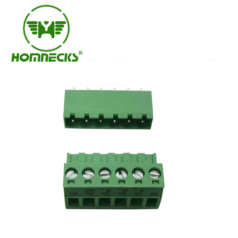
Robots have become an integral part of various industries, revolutionizing manufacturing processes and increasing efficiency. Behind the scenes, sophisticated robot control systems ensure smooth operation and accurate execution of tasks. One crucial component in these systems is the pluggable terminal block, which plays a vital role in providing reliable connections. In this article, we will explore the applications of pluggable terminal blocks in robot controllers.


Terminal blocks are a fundamental part of any electrical system, including robot controllers. Specifically, the 3-pole terminal block offers a versatile solution for connecting multiple devices within the control panel. Its design allows for the effortless connection of wires, enabling secure and efficient power distribution. By utilizing 3-pole terminal blocks in robot controllers, engineers can streamline wiring and optimize the overall control system.


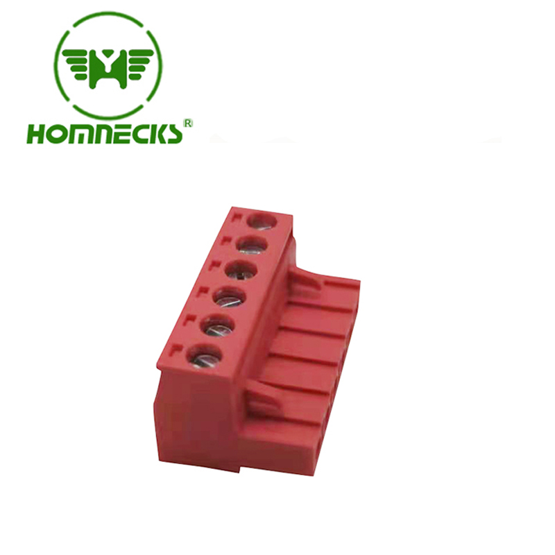
Screw type terminal blocks are widely used in robot control systems due to their robust and reliable nature. These blocks feature a screw mechanism, ensuring a strong connection between wires and terminals. This mechanism also enables easy installation and maintenance, reducing downtime. The availability of various sizes and configurations of screw type terminal blocks makes them suitable for diverse robot controller applications, offering flexibility and adaptability.

pcb terminal blocks

In complex robot control systems, the need for modular and expandable solutions is paramount. This is where screw terminal block connectors come into play. These connectors provide an additional layer of flexibility by allowing quick and secure connections between different modules or subsystems. By utilizing screw terminal block connectors, engineers can easily integrate or replace components, simplifying maintenance and reducing system downtime.

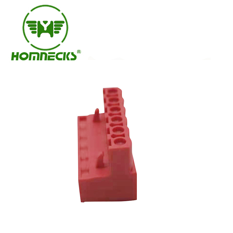
Printed Circuit Boards (PCBs) are an integral part of robot control systems, serving as the nerve center for signal and power distribution. PCB terminal blocks offer a reliable and space-efficient solution for connecting wires to PCBs. These terminal blocks feature a compact design, allowing for high-density PCB layouts without compromising on functionality. The ease of installation and secure connections provided by PCB terminal blocks make them a preferred choice in robot controller design.

When it comes to PCB connections in robot controllers, PCB terminal connectors play a crucial role. These connectors allow for the quick and secure connection of wires to the PCB, facilitating efficient signal transmission and power distribution. With their compact design and reliable performance, PCB terminal connectors ensure the stability and integrity of the robot control system, enabling precise and error-free operation.


In addition to traditional PCB terminal blocks, PCB pin terminals offer a unique solution for specific robot controller applications. These terminals feature a pin design that directly interfaces with PCBs, eliminating the need for additional terminal blocks or connectors. PCB pin terminals provide a secure and space-saving connection solution, making them ideal for compact robot control systems where minimizing size and weight is crucial.


In conclusion, pluggable terminal blocks are essential components in robot control systems, providing reliable and efficient connections. The 3-pole terminal block, screw type terminal blocks, screw terminal block connectors, PCB terminal blocks, PCB terminal connectors, and PCB pin terminals all play vital roles in ensuring seamless operation and flexibility within the control panel. When it comes to these products' manufacturers, HONG YI-HOMNECKS+PCB TERMINAL BLOCK stands out for its exceptional product quality, durability, and extensive range of offerings. Moreover, the company's commitment to excellent customer service and technical support makes HONG YI-HOMNECKS the ideal choice for seamless integration of terminal block solutions into robot control systems.


READ MORE >

Ensuring Smooth Operation of Servo Control Systems with 2 Pole Terminal Blocks

2 pole terminal block

In modern industrial applications, servo control systems play a crucial role in precise motion control. To ensure the seamless operation of these systems, the proper wiring and connection of components are essential. One vital component that facilitates reliable and efficient connections is the 2 pole terminal block. In this article, we will explore the significance of  3 pin terminal block  and their role in safeguarding the smooth operation of servo control systems.


A 2 pole terminal block acts as a bridge between the control system and various devices, enabling secure and dependable electrical connections. It provides the necessary interface for power transfer, signal transmission, and control within the servo control system. Whether it is connecting motors, sensors, or other components, 2 pin screw connector ensures optimal performance and minimizes the risk of signal loss or disconnection.

3 pin terminal block

The adaptability of a terminal block 2 pole makes it suitable for a wide range of applications. With its design supporting screw connectors, 2 pin screw terminal   provides a secure and stable connection, ensuring the integrity of the electrical circuit. Additionally, the inclusion of 2 poles enables the connection of multiple devices or circuits, enhancing flexibility in system configuration and expansion.


Terminal blocks play a vital role in simplifying wiring and installation processes, reducing downtime and improving efficiency. In the case of 2 way terminal block , their user-friendly design and intuitive connection interface make installation quick and hassle-free. The secure screw terminals ensure reliable connections even in demanding industrial environments, preventing the risk of loose or disconnected wires.


When it comes to high-quality 2 pole terminal blocks, HONG YI-HOMNECKS stands out as a reliable manufacturer and supplier. Their extensive range of PCB terminal blocks, including 3 pin terminal blocks and 2 pole terminal blocks, ensures seamless connectivity in servo control systems. With a commitment to providing superior products, HONG YI-HOMNECKS offers durable and reliable solutions that guarantee the smooth operation of your applications.


In summary, 2 pole terminal blocks play a vital role in ensuring the smooth operation of servo control systems. Their versatility, reliability, and ease of installation make them an indispensable component for establishing secure electrical connections. When looking for trusted solutions, HONG YI-HOMNECKS+PCB Terminal Blocks provide effective and reliable options backed by their commitment to quality and service.


READ MORE >

Exploring the Market Potential of 3 Way Terminal Blocks

3 way terminal block

Introduction:

In today's rapidly evolving technological landscape, the demand for efficient and reliable electrical connections continues to grow. One product that plays a crucial role in various industries is the 3 way terminal block. Designed to facilitate secure and organized terminal 3 pin, these terminal blocks offer immense potential in ensuring smooth operations for various applications. This article delves into the market prospects and benefits of 3 way terminal blocks.


Versatile Applications of 3 Way Terminal Blocks:

3 way terminal blocks find extensive applications in industries such as automation, machinery, and electrical systems. With their capability to accommodate multiple connections, terminal block 3 pin  provide a reliable solution for complex wiring setups. Whether it's connecting sensors, actuators, or control devices, the versatility of 3 pin screw terminal block connector makes them essential components in today's advanced systems. Manufacturers like HONG YI-HOMNECKS cater to diverse industrial needs by offering a range of high-quality terminal block options, including 3-pin variants.

terminal block connector 3 pin

Enhanced Connectivity with 3 Pin Screw Terminal Block Connectors:

The integration of screw terminal block connectors simplifies the installation and maintenance processes of 3 way terminal blocks. By utilizing screw-based connections, these terminal blocks ensure secure and vibration-resistant electrical contacts. The 3 pin screw terminal block connectors provide a reliable and stable interface, minimizing the risk of loose connections and electrical faults. Users can trust HONG YI-HOMNECKS' expertise in providing top-notch terminal block connector 3 pin connectors for seamless connectivity.


Streamlined Wiring with 3 Pin Terminal Block Connectors:

Terminal block connectors with 3 pins bring efficiency and convenience to wiring tasks. By offering a compact and organized solution for connecting multiple wires, these terminal blocks eliminate the messiness of individual wire connections. The design of 3 pin terminal block connectors enables easy identification and routing of wires, saving time during installation and future maintenance. HONG YI-HOMNECKS, a leading manufacturer and supplier in the industry, delivers high-quality 3 pin terminal block connectors for hassle-free wiring solutions.


Increased Reliability of 3 Way Terminal Blocks:

The reliability of electrical systems heavily depends on the quality of terminal blocks used. 3 way terminal blocks offer exceptional durability, ensuring long-lasting performance in demanding environments. With features such as corrosion-resistant materials and robust construction, these terminal blocks provide a secure and stable connection, even in harsh conditions. HONG YI-HOMNECKS, renowned for its commitment to quality, ensures that their 3 way terminal blocks meet industry standards, enhancing system reliability and minimizing downtime.


Future Market Trends and Opportunities:

The market for 3 way terminal blocks is poised for significant growth as industries continue to demand reliable and efficient electrical connections. Rapid advancements in automation, smart devices, and renewable energy systems fuel the need for innovative terminal block solutions. Manufacturers like HONG YI-HOMNECKS, with their dedication to research and development, are at the forefront of introducing advanced 3-way terminal block technologies and expanding their product offerings. As the industry evolves, the demand for versatile, high-quality, and feature-rich 3 way terminal blocks is expected to soar.


The market outlook for 3 way terminal blocks is immensely promising due to their versatile applications and significant benefits in electrical connectivity. With the convenience of 3 pin screw terminal block connectors and the seamless wiring facilitated by 3 pin terminal block connectors, these components are crucial for ensuring reliable and efficient electrical connections. As the market continues to evolve, HONG YI-HOMNECKS, a trusted terminal block manufacturer and supplier, remains committed to meeting industry demands through their premium range of 3 way terminal blocks and associated connectors, solidifying their position as a leader in the field.


READ MORE >

Proper Wiring Techniques for PCB Board Terminal Blocks

2 pin terminal connector

When it comes to electrical connections in PCB boards, using the right terminal blocks is crucial for ensuring reliable and safe performance. In this article, we will explore the importance of proper wiring techniques for PCB board terminal blocks and how they contribute to efficient and effective electrical connections. Let's delve into the details.


Choosing the Right Terminal Connector:

The selection of an appropriate terminal connector is essential for achieving optimal performance. The 2-pin terminal connector provides a reliable and secure connection for low-power applications. Similarly, the 2-pin screw terminal connector offers the advantage of easy installation and maintenance. It ensures a solid and stable connection, preventing any signal loss or disruption.


Ensuring a Secure Connection:

When dealing with PCB board terminal blocks, it is crucial to establish a secure connection. The 2-pin screw terminal block connector allows for a tight and precise connection, reducing the risk of loose or weak connections. This ensures the efficient flow of signals between components and minimizes potential signal interference.


3 pole terminal block

Enhanced Safety with Barrier Terminal Blocks:

For applications that require higher safety measures, the PCB barrier terminal block comes into play. It offers additional insulation and protection, reducing the risk of short circuits and accidental contact. With its design, the barrier terminal block prevents damage to the conductors and minimizes the chances of electrical hazards.


Effective Wiring with 3-Pole Terminal Blocks:

In scenarios where multiple connections are necessary, the 3-pole terminal block becomes essential. It provides a convenient solution for connecting three conductors together, ensuring a neat and organized wiring arrangement. The 3-pole terminal block simplifies the installation process and enables efficient power distribution and control within the PCB board.


The Advantages of HONG YI-HOMNECKS+PCB Terminal Blocks:

Recognized as a leading manufacturer and supplier of high-quality terminal blocks, HONG YI-HOMNECKS ensures exceptional performance and reliability. Their PCB terminal blocks offer superior conductivity, durability, and optimal signal transfer. With a wide range of options, including 2-pin and 3-pole terminal blocks, they cater to various application requirements.


HONG YI-HOMNECKS' Commitment to Exceptional Service:

In addition to their top-notch products, HONG YI-HOMNECKS prioritizes customer satisfaction and provides excellent service. Their team of experts is dedicated to assisting customers in selecting the right terminal blocks for their specific needs. With HONG YI-HOMNECKS, you can expect timely support, technical guidance, and reliable solutions that ensure successful project outcomes.


Properly wiring PCB board terminal blocks is essential for achieving efficient signal transmission and maintaining a secure electrical connection. By choosing the right terminal connector, implementing secure connections, and utilizing appropriate terminal blocks like 2-pin screw terminal connectors, barrier terminal blocks, and 3-pole terminal blocks, you can ensure optimal performance and safety. For high-quality terminal blocks and exceptional service, trust HONG YI-HOMNECKS+PCB Terminal Blocks to meet your requirements with precision and reliability.

READ MORE >

Basics of valves

In the fluid piping system, the valve is a control element, its main role is to isolate the equipment and piping system, regulate flow, prevent backflow, regulate and discharge pressure.

Valves can be used to control the flow of various types of fluids such as air, water, steam, various corrosive media, slurries, oils, liquid metals and radioactive media. Since the selection of the most suitable valve for the piping system seems to be very important, it becomes vital to understand the characteristics of the valve and the steps and basis for selecting the valve.


The classification of the valve

Valves can be divided into two main categories:

1. Automatic valves

Relying on the medium (liquid, gas) the ability to act on its own valves.

Such as check valves, safety valves, control valves, traps, pressure reducing valves.

2. Drive the valve

With manual, electric, hydraulic, pneumatic to manipulate the action of the valve.

Such as gate valves, globe valves, throttle valves, butterfly valves, ball valves, plug valves and so on.

According to the structural characteristics, according to the direction of the closing member relative to the valve seat movement can be divided into:

(1) Gate shape: the closing member moves along the center of the valve seat;

(2) Gate shape: the closing member moves along the center of the vertical valve seat;

(3) Plunger and ball: the closing member is a plunger or ball, rotating around its own centerline;

(4) Rotary opening shape: the closing member rotates around the axis outside the valve seat;

(5) Disc shape: the disc of the closing member, rotating around the axis inside the valve seat;

(6) Slide valve shape: the closing member slides in the direction perpendicular to the passage.

According to the use, according to the different uses of the valve can be divided into:
(1) Open and close with: used to connect or cut off the pipeline medium, such as globe valves, gate valves, ball valves, butterfly valves and so on.
(2) Check: used to prevent the medium backflow, such as check valves.
(3) Regulation: used to adjust the pressure and flow of the medium, such as regulating valves, pressure reducing valves.
(4) Distribution: used to change the direction of media flow, distribution of media, such as three-way plug, distribution valves, slide valves.
(5) Safety valve: in the medium pressure exceeds the specified value, used to discharge excess media, to ensure the safety of piping systems and equipment, such as safety valves, accident valves.
(6) Other special purposes: such as traps, air release valves, sewage valves, etc..
According to the drive mode, according to the different drive mode can be divided into:
(1) Manual: with the help of handwheels, handles, levers or sprockets, etc., there are manpower drive, transmission of large torque is equipped with worm gears, gears and other deceleration devices.
(2) Electric: with the help of motor or other electrical devices to drive.
(3) Hydraulic: with the help of (water, oil) to drive.
(4) Pneumatic: driven by compressed air.
According to the pressure, according to the nominal pressure of the valve can be divided into:
(1) Vacuum valves: absolute pressure <0.1Mpa that is, 760mm Hg high valves, usually mm Hg or mm water column pressure.
(2) Low-pressure valves: nominal pressure PN ≤ 1.6Mpa valves (including PN ≤ 1.6MPa steel valves)
(3) Medium pressure valve: nominal pressure PN2.5-6.4MPa valve.
(4) High-pressure valve: nominal pressure PN10.0-80.0MPa valve.
(5) Ultra-high pressure valve: nominal pressure PN ≥ 100.0MPa valve.
According to the temperature of the medium, according to the temperature of the medium when the valve works can be divided into:
(1) Ordinary valves: applicable to the medium temperature -40 ℃ ~ 425 ℃ valve.
(2) High-temperature valves: for media temperature 425 ℃ ~ 600 ℃ valve.
(3) Heat-resistant valves: for media temperature of 600 ℃ above the valve.
(4) Low-temperature valves: for media temperature -150 ℃ ~ -40 ℃ valve.
(5) Ultra-low temperature valves: for media temperature -150 ℃ below the valve.
According to the nominal diameter, according to the nominal diameter of the valve can be divided into:
(1) Small diameter valve: nominal diameter DN <40mm valve.
(2) Medium caliber valves: nominal diameter DN50 ~ 300mm valve.
(3) Large caliber valves: nominal diameter DN350 ~ 1200mm valve.
(4) Large caliber valves: nominal diameter DN ≥ 1400mm valve.
According to the way of connection with the pipeline, according to the valve and pipeline connection can be divided into:
(1) Flange connection valve: valve body with a flange, and the pipeline using flange connection valve.
(2) Threaded connection valve: valve body with internal or external threads, and the pipeline using threaded connection valve.
(3) Welded connection valve: valve body with weld, and the pipeline using welded connection valve.
(4) Hoop connection valve: the valve body with a clamp port, and the pipeline using the hoop connection valve.

(5) Ferrule connection valve: the use of ferrule and pipe connection valve.


The characteristics of the valve

Valve characteristics generally have two kinds of characteristics, the use of characteristics and structural characteristics.

1. The use of characteristics

It determines the main use of the valve performance and scope of use, belonging to the use of the valve characteristics:

  • Valve category (closed-loop valves, regulating valves, safety valves, etc.);
  • Product type (gate valve, globe valve, butterfly valve, ball valve, etc.);
  • Materials of the main parts of the valve (valve body, valve cover, valve stem, valve flap, sealing surface);
  • Valve transmission mode, etc.

2. Structural characteristics

It determines the valve installation, repair, maintenance and other methods of some structural characteristics, belonging to the structural characteristics:

  • Valve structure length and overall height, and pipeline connection form (flange connection, threaded connection, clamped hoop connection, external threaded connection, welded end connection, etc.);
  • The form of sealing surface (inlay ring, threaded ring, surfacing, spray welding, valve body body);
  • The form of valve stem structure (rotating stem, lifting stem) and so on.


The selection of the steps and basis of the valve

1. Selection steps

(1) Clearly the use of the valve in the equipment or device to determine the working conditions of the valve: applicable media, operating pressure, operating temperature, etc..

(2) Determine the nominal diameter of the pipeline connected to the valve and connection: flange, threaded, welded, etc..

(3) Determine the way to operate the valve: manual, electric, electromagnetic, pneumatic or hydraulic, electrical linkage or electro-hydraulic linkage.

(4) According to the pipeline medium, working pressure, working temperature to determine the selected valve shell and inner parts of the material: gray cast iron, malleable cast iron, ductile iron, carbon steel, alloy steel, stainless acid-resistant steel, copper alloy, etc..

(5) Select the type of valve: closed-circuit valves, regulating valves, safety valves and so on.

(6) Determine the type of valve: gate valves, globe valves, ball valves, butterfly valves, throttle valves, safety valves, pressure reducing valves, steam traps, etc.

(7) Determine the parameters of the valve: for automatic valves, according to the different needs of the first to determine the allowable flow resistance, discharge capacity, back pressure, etc., and then determine the nominal diameter of the pipeline and the diameter of the valve seat hole.

(8) Determine the geometric parameters of the selected valve: structural length, flange connection form and size, open and close the valve after the height direction of the size, the size and number of bolt holes to connect, the entire valve dimensions, etc..

(9) The use of existing information: valve catalogs, valve product samples, etc. to select the appropriate valve products.

2. The basis for selecting the valve

In understanding the steps to master the selection of valves at the same time, should further understand the basis for selecting the valve.

(1) The purpose of the selected valve, the use of working conditions and manipulation control.

(2) The nature of the working medium: working pressure, working temperature, corrosive properties, whether it contains solid particles, whether the medium is toxic, whether it is flammable, explosive media, the viscosity of the medium and so on.

(3) The requirements of the valve fluid characteristics: flow resistance, discharge capacity, flow characteristics, sealing grade and so on.

(4) Installation size and size requirements: nominal diameter, connection with the pipeline and connection size, dimensions or weight limitations.

(5) Of the valve product reliability, service life and explosion-proof performance of electric devices and other additional requirements.

Attention should be paid when selecting parameters:

If the valve is to be used for control purposes, the following additional parameters must be determined: method of operation, the maximum and minimum flow requirements, the pressure drop in normal flow, the pressure drop when closed, the maximum and minimum inlet pressure of the valve.

According to the above selection of valves based on the basis and steps, reasonable and correct selection of valves must also be a detailed understanding of the internal structure of various types of valves, in order to be able to prioritize the selection of valves to make the right choice.

The final control of the pipeline is the valve. Valve opening and closing parts of the control of the medium in the pipeline beam way, the shape of the valve flow path so that the valve has a certain flow characteristics, in the selection of piping system is most suitable for the installation of the valve must take this into account.

Selection of valves should follow the principles:
(1) Shut-off and open medium with the valve
Flow path for the straight-through valve, its flow resistance is small, usually selected as a cut-off and open medium with the valve. Downward closing type valve (globe valve, plunger valve) due to its flow path zigzag, flow resistance is higher than other valves, so less selection. Allow a higher flow resistance of the occasion, you can choose to close the valve.
(2) Valves for flow control
Usually choose the valve that is easy to adjust the flow rate as the control flow rate. Downward closing type valves (such as globe valves) is suitable for this purpose, because its seat size is proportional to the stroke between the closing member. Rotary valves (plug valves, butterfly valves, ball valves) and flexure body type valves (clamp valves, diaphragm valves) can also be used for throttling control, but are usually only applicable within a limited range of valve sizes. Gate valve is a disc-shaped gate on the circular valve seat mouth to do cross-cutting movement, it is only close to the closing position, can better control the flow, so usually not used for flow control.
(3) Reversing and diverting valves
According to the need for commutation and diversion, this valve can have three or more channels. Plug valves and ball valves are more suitable for this purpose, therefore, most of the valves used for commutation of flow diversion are selected one of these valves. But in some cases, other types of valves, as long as the two or more valves properly connected to each other, can also be used for reversing the flow.
(4) Valves for media with suspended particles

When the medium with suspended particles, the most suitable for the use of its closure along the sealing surface of the sliding with the wiping effect of the valve. If the closing member of the seat of the back and forth movement is vertical, then it may be entrapped particles, so this valve unless the sealing surface material can allow embedded particles, otherwise only suitable for basic clean media. Ball valves and plug valves in the opening and closing process of the sealing surface are wiping effect, so it is suitable for use in the medium with suspended particles.


The valve selection instructions

1. Gate valve selection

In general, the gate valve should be preferred. In addition to the gate valve for steam, oil and other media, but also for the media containing granular solids and viscosity, and for the venting and low vacuum system valves. For media with solid particles, the gate valve body should be with one or two blow holes. For low-temperature media, should be used for low-temperature special gate valve.

2. Globe valve selection instructions

Globe valve is suitable for the fluid resistance requirements are not strict pipeline, that is, the pressure loss is not a big consideration, as well as high temperature, high pressure media pipeline or device, suitable for DN <200mm steam and other media pipeline; small valves can be used to select the globe valve, such as needle valves, instrumentation valves, sampling valves, manometer valves, etc.; Globe valve flow regulation or pressure adjustment, but the regulation of the accuracy of the requirements of the high, and the diameter of the pipeline and Comparison of hours, it is appropriate to use the globe valve or throttle valve; for highly toxic media, it is appropriate to use the bellows sealed globe valve; but the globe valve should not be used for viscosity of the medium and contain particles easy to precipitate the medium, but also should not be used as a bleeder valve and the valve of the low-vacuum system.

3. Ball valve selection instructions

Ball valves are suitable for low temperature, high pressure, viscosity of the medium. Most ball valves can be used in the medium with suspended solid particles, according to the material requirements of the seal can also be used for powdery and granular media; full-channel ball valves are not suitable for flow regulation, but suitable for the requirements of rapid opening and closing occasions, to facilitate the realization of the accident emergency cut off; usually in the sealing performance is strict, wear and tear, indentation of the channel, open and close quickly, high-pressure cut-off (differential pressure is large), low-noise, cavitation phenomenon, the operating torque is small, the fluid resistance. Torque is small, small fluid resistance in the pipeline, the recommended use of ball valves; ball valves are suitable for lightweight structure, low-pressure cut-off, corrosive media; ball valves or low-temperature, deep-cold media, the most ideal valve, low-temperature media piping systems and devices, it is appropriate to choose to add the bonnet of the low-temperature ball valves; selection of floating ball ball valves when the seat material should undertake the ball and the working medium of the load, the large-diameter ball valves need to be larger when operating Force, DN ≥ 200mm ball valve should be selected worm gear drive form; fixed ball valve for larger caliber and higher pressure occasions; in addition, for the process of highly toxic materials, combustible media pipeline ball valve, should have a fire prevention, anti-static structure.

4. Throttle valve selection instructions

Throttle valve is suitable for medium temperature is low, high pressure occasions, suitable for the need to regulate the flow and pressure of the parts, does not apply to viscosity and contain solid particles of the medium, should not be used as a partition valve.

5. Plug valve selection instructions

Plug valves are suitable for occasions requiring rapid opening and closing, generally not applicable to steam and higher temperature media, for lower temperature, viscosity of the media, but also applicable to the media with suspended particles.

6. Butterfly valve selection instructions

Butterfly valve is suitable for larger caliber (such as DN>600mm) and short structure length requirements, as well as the need for flow regulation and opening and closing requirements for rapid occasions, generally used for temperature ≤ 80 ℃, pressure ≤ 1.0MPa water, oil and compressed air and other media; due to the butterfly valve relative to the gate valve, the ball valve pressure loss is relatively large, the butterfly valve is suitable for pressure loss requirements are not stringent piping system.

7. Check valve selection instructions

Check valve is generally applicable to clean media, should not be used for solid particles and viscosity of the medium.

  • When DN ≤ 40mm, it is appropriate to use lift check valve (only allowed to be installed in the horizontal pipeline);
  • When DN = 50 ~ 400mm, it is appropriate to use the rotary lift check valve (in the horizontal and vertical pipeline can be installed, such as installation in the vertical pipeline, the media flow direction should be from the bottom up);
  • When DN ≥ 450mm, it is appropriate to use buffer type check valve;
  • When DN = 100 ~ 400mm can also choose to use the clamp type check valve;

Swing check valve can be made into a very high working pressure, PN can reach 42MPa, according to the shell and sealing material can be applied to any working medium and any working temperature range. The medium is water, steam, gas, corrosive media, oil, pharmaceuticals and so on. Medium working temperature range between -196 ~ 800 ℃.


8. Diaphragm valve selection instructions

Diaphragm valve is suitable for working temperature less than 200 ℃, pressure less than 1.0MPa oil, water, acidic media and media containing suspended solids, not for organic solvents and strong oxidizing agents media; abrasive particulate media should be selected weir diaphragm valve, weir diaphragm valve to refer to the flow characteristics of the table; viscous fluids, cement slurry, and precipitation media should be selected through the type of diaphragm valve; in addition to the specific requirements, diaphragm valve Should not be used for vacuum piping and vacuum equipment.

Valve applications, frequency of operation and service varies greatly, to control or eliminate even the slightest leakage, the most important, the most critical equipment is still the valve. Learning the proper selection of valves is critical.


READ MORE >

Common faults and maintenance methods of corrosion-resistant self-priming pumps

What are the common faults and maintenance methods of corrosion-resistant self-priming pumps? As described below:


The pump head part of corrosion-resistant self-priming pump:


1. Most cases where the casing is electrified have water seal damage, causing water to seep into the motor through the shaft and deteriorate the insulation performance. This can be repaired by replacing the water seal or drying the motor.


2. Although the motor is running normally, the water output is low or not at all. In this case, the sealing of the pump must be checked first. When checking, first unplug the power plug, block the suction port with your hand, fill the pump with water, hold the mouth with your mouth and blow air inside with force, observe whether the pump head leaks water, that is, if the seal is damaged. Common faulty parts include the suction port gasket, outlet gasket, and impeller cover gasket, which should be replaced during maintenance.


Corrosion resistant self-priming pump motor part:

1. There is no response even after connecting the power supply. This situation is mostly caused by short circuits in the power plug, power outlet, and motor coil.


2. Difficult to start or unable to start, accompanied by a buzzing sound. During inspection, a small bamboo blade can be used to quickly move the wind shear in the driving direction. If the motor runs quickly, it indicates that the starting capacitor or starting coil is damaged. Please replace the capacitor with the same capacity or repair the starting winding. If it is a problem with the motor, it is mostly caused by mechanical failures of the motor and pump head, such as bearing damage, impeller adhesion, etc.


3. The motor can work, but the speed is slow and the casing is overheated, with a burnt smell. Most of them are caused by short circuits in the motor coils, and the motor needs to be disassembled. Depending on the damage, measures such as welding, jumper wires, isolation, and rewinding should be taken for repair.


4. There is loud noise and vibration during homework. In most cases, due to bearing damage or improper fitting between the bearing and the housing, the motor should be disassembled and inspected. If the bearing is damaged, it should be replaced.

READ MORE >

Detailed Introduction to Commonly Used Valves in Water Treatment Equipment

There are many types of valves used in water treatment, such as: gate valves, globe valves, butterfly valves, check valves, plug valves, valves, safety valves, and pressure reducing valves.


1. Gate Valve

Usages:

This is the most commonly used on-off valve, which uses a gate (i.e., the opening and closing member, referred to as a or door in a gate valve, and the valve seat is referred to as a gate seat or door seat) to connect (fully open) and shut off ( closed) the medium in the pipeline. It is not allowed to be used as a throttle, and during use, it should avoid partially opening the gate because the of high-speed flowing media can accelerate the damage to the sealing surface. The gate moves up and down in a plane perpendicular to the centerline of the gate seat, like a door, to shut off the medium in the pipeline, hence it is called a gate valve.


Features:

  1. Low fluid resistance. The internal medium passage of the valve body is straight, the medium flows in a straight line, and fluid resistance is small.
  2. Less force required for opening and closing. Compared with globe valves, gate valves require less force to open and close because the gate perpendicular to the direction of the medium flow, whether opening or closing.
  3. High height and long opening and closing time. The gate has a large travel distance and the lifting is done through a screw.
  4. Water hammer is unlikely to occur. This is due to the long closing time.
  5. The medium can in any direction on both sides, making it easy to install. The passages on both sides of the gate valve are symmetrical.
  6. Short structural length (the between the two connection ends of the shell).
  7. The sealing surface is prone to wear, affecting the service life. During opening and closing, the gate and valve seat's two sealing surfaces rub against each other, and under the action of medium pressure, they are prone to wear, affecting the sealing performance and shortening service life.
  8. High price. There are many contact sealing surfaces, the processing is complex, especially the sealing surface on the gate seat is difficult to process and there are many parts.


2. Globe Valve

Usages:

The globe valve is a type of closed circuit valve that controls the opening and closing of pipelines by moving the valve disc (the closing element the globe valve) along the centerline of the valve seat passage. The globe valve is generally suitable for various pressures and temperatures within the specified standard range, for liquid and gas media, but it is not suitable for conveying liquids containing solid precipitates or crystalline substances. In low-pressure pipelines, globe valves can also be to regulate the flow of media in the pipeline. Due to structural limitations, the nominal diameter of globe valves is below 250mm. In pipelines with media pressure and higher flow velocity, the sealing surface will wear out quickly. Therefore, when flow regulation is required, a throttle valve must be used.

Features:

  1. The wear and scratch of the sealing surface are not serious, so the work is more reliable and the service life is long.
  2. The sealing surface area is small, the structure is simple, the working hours required to manufacture the sealing surface and the expensive materials required for the sealing ring are than those of the gate valve.
  3. The valve disc travel is small when opening and closing, so the height of the globe valve is small. It is to operate.
  4. The valve disc is moved by the screw thread, so there is no sudden opening and closing phenomenon, and it is not easy to cause "water hammer" phenomenon.
  5. The opening and closing torque is large and it is laborious to open and close. When closing, the movement direction of valve disc is opposite to the direction of the medium movement pressure, so it is necessary to overcome the action force of the medium, thus the opening and closing torque large, which affects the application of large diameter globe valves.
  6. The flow resistance is large. Among various shut-off valves, the flow resistance of the globe is the largest (the medium passage is more tortuous).
  7. The structure is more complex.
  8. The medium flow direction is unidirectional. It ensure that the medium flows from bottom to top.


3. Butterfly Valve

Usages:

A butterfly valve is a rotary valve that uses a disc-shaped (also known as a butterfly plate) closure member to open and close the passage rotating it 90° or approximately 90°. The movement of the butterfly valve's closure member has a wiping action, making most butterfly valves suitable media with suspended solid particles. There are two common types of butterfly valves: wafer type and flanged type. Wafer type butterfly valves are connected between two flanges using double-headed bolts, while flanged type butterfly valves have flanges on the valve itself, and are connected to the pipeline flanges using bolts.

Features:


  1. Compact size, short length, simple structure, and light weight.
  2. Easy operation, quick opening and closing, only need rotate the valve flap 90°.
  3. Good sealing and regulating performance, using rubber as the sealing ring, with good compression and resilience (i., will not harden), so the sealing performance is good. The valve flap can perform sensitive flow control when opened from 15° to 70.
  4. Small operating torque and fluid resistance. According to measurements, the fluid resistance of butterfly valves is less than that of other types of valves except ball.
  5. Due to the limitations of the sealing material, the operating pressure and working temperature range of butterfly valves are relatively small.


4. Check Valve

Usages and Features:

A check valve, also known as a non-return valve, is a type of valve that prevents the backflow of media in pipelines. opens when the media flows in the forward direction and automatically closes when the media flows in the reverse direction. It is typically used in pipelines where media is not allowed flow in the opposite direction, to prevent damage to equipment and machinery from reverse flow. When a pump stops running, it prevents the rotation of the pump in the direction. In pipelines, check valves are often used in series with shut-off valves. This is because the seal of a check valve is relatively poor, and when media pressure is low, a small amount of media may leak, so a shut-off valve is needed to ensure the pipeline is closed. A foot valve is also type of check valve that must be submerged in water and is specifically installed at the front end of the suction pipe of a pump that cannot self-prime or does have a vacuum suction to draw water.


5. Cock Valve

Usages:

The plug valve refers to a type of valve where the closure member (a plug with a passage) rotates around the centerline of the valve to achieve opening or closing. It is widely used in pipelines conveying media with temperatures ≤120℃. Due to the thermal expansion of the plug and the body, it may cause jamming, so it is less used at high temperatures. The plug valve can be used to cut off the flow of media, and can also be used as a control valve, three-way valve, four-way valve, or distribution valve, as well as to change the direction of the media flow.

Features:


  1. The resistance is relatively small when the medium passes through, especially for the straight-through type.
  2. Simple structure, light weight, size, convenient and fast operation.
  3. When there is considerable pressure of the medium in the pipeline, "water hammer" may occur due to rapid closure.
  4. Turning the plug is laborious (large sealing surface).
  5. Can be installed horizontally or vertically.
  6. The cone surface in contact between the valve body the plug is large, which is prone to wear during use and affects the seal. If a sealed structure is adopted, injecting grease into the sealing surface to form oil film can improve the sealing performance.


6. Throttle Valve

Usages and Features:

The throttle valve regulates the flow and pressure of the pipeline medium by changing the cross-sectional area of the valve passage. The smaller the cross area, the greater the resistance to the medium, and the smaller the flow. In fact, all kinds of shut-off valves can regulate flow, but because the between the closure member and the valve stem is movable, there is a gap at the connection, so during the process of change, the rise and fall of the member is not easily proportional to the change in passage area, resulting in poor regulation performance. Therefore, a special throttle valve is used for regulation. The throttle valve be used as a shut-off valve, generally it does not have a sealing surface, even if it has a sealing surface, the sealing surface is quickly eroded the action of high-speed medium, losing its sealing property. Therefore, the throttle valve on the pipeline cannot replace the function of a shut-off valve.


7. Safety Valve


Usages and Features:

A safety valve is a protective valve. It is installed on pressurized equipment, containers, and pipelines. The safety valve remains closed under conditions. When the pressure of the medium in the protected pipeline exceeds the specified value, the valve disc automatically opens to discharge the excess medium, thereby reducing the; and when the medium pressure returns to within the specified range, it automatically closes. The safety valve ensures the safe operation of the system and equipment on the pipeline Safety valves are widely used on boilers, compressor air receivers, high-pressure containers, and pipelines where the working pressure of the medium may exceed the allowed value and cause hazards.


8. Pressure Reducing Valve

Usages and Features:

The pressure reducing valve reduces the pressure of the medium in the equipment container or pipeline to the specified pressure, and maintains the outlet pressure within a range despite changes in inlet pressure or outlet flow. The pressure reducing valve achieves pressure reduction by regulating the flow, making it suitable for the needs of various production processes.


READ MORE >