Why Are More Engineers Choosing 5A Duplex Stainless Steel Gate Valves for Harsh Operating Conditions?
Introduction
In industrial fluid control systems, gate valves, as a type of shut-off valve, have long played a key role in opening and closing operations. With increasingly complex operating conditions, higher demands are being placed on valves in terms of corrosion resistance, wear resistance, and service life.
Among the many available materials, duplex stainless steel (ASTM A995 5A) combined with hardfacing using Stellite (STL, cobalt-based alloy) has gradually become the preferred choice of engineers for harsh operating conditions. This configuration not only ensures the stability of the valve body in corrosive and high-pressure environments but also significantly enhances the durability and reliability of the sealing surface.
Material Analysis
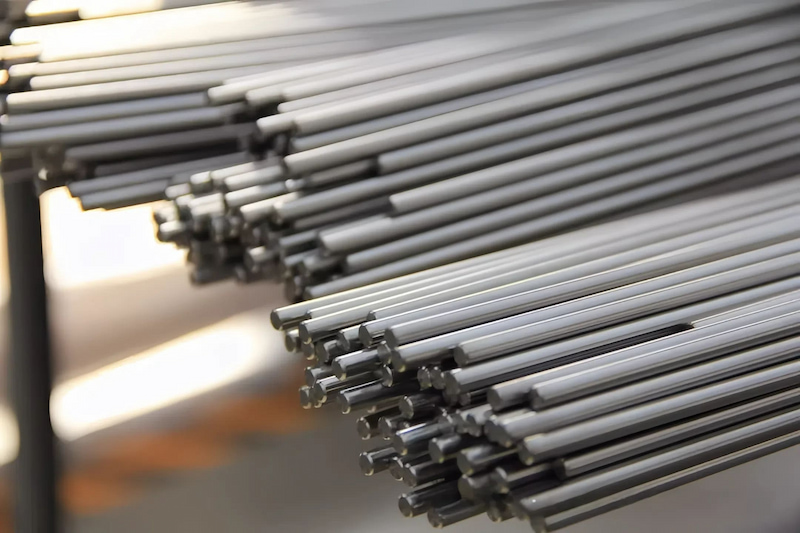
1. ASTM A995 5A Duplex Stainless Steel
● Advantages of duplex structure: Composed of ferrite and austenite, combining high strength with good toughness.
● Excellent corrosion resistance: Effectively resists chloride pitting, crevice corrosion, and stress corrosion cracking.
● Stable mechanical properties: Maintains strong load-bearing capacity under high-pressure and high-strength conditions.
2. STL (Stellite Cobalt-Based Alloy Hardfacing)
● Outstanding wear resistance: Withstands severe erosion and mechanical abrasion.
● Extended sealing surface lifespan: Ensures stability of the seat and sealing surface, reducing leakage issues caused by wear.
Performance Advantages
Corrosion Resistance: Suitable for seawater, acidic media, and sour oil and gas environments.
● Mechanical Strength: High-strength structure ensures pressure-bearing capacity with excellent fatigue resistance.
● Reliable Sealing: STL hardfaced sealing surfaces provide superior wear resistance, reducing the need for frequent maintenance.
● Extended Service Life: Material advantages significantly lower the total lifecycle cost of the valve.
Application Conditions
The 5A duplex stainless steel gate valve is widely applicable in the following conditions:
● Offshore oil and gas production platforms
● Chemical and petrochemical industries (acidic and high-chloride environments)
● Seawater desalination and water treatment systems
● Cryogenic conditions
● Industrial pipelines with high chloride-induced corrosion risks
Conclusion
The ASTM A995 5A duplex steel + STL hard-facing welded gate valve, with its exceptional corrosion resistance, strength, and sealing reliability, is the ideal choice for demanding operating conditions. It not only maintains stability in high-corrosion and high-erosion environments but also effectively reduces maintenance frequency and the total lifecycle cost. In the future, with the ongoing expansion of energy development, marine engineering, and complex operating conditions, the application prospects of the 5A duplex steel gate valve will be even broader.
Q&A
Q1: What industries is the 5A duplex steel gate valve suitable for?
A1: It is widely used in pipeline systems for the oil and gas, chemical, seawater desalination, and high-chloride environments.
Q2: What are the advantages of the 5A duplex steel gate valve compared to regular stainless steel gate valves?
A2: The 5A duplex steel offers superior corrosion resistance and mechanical strength, while the STL hard-facing ensures wear resistance of the sealing surface. Together, they significantly extend the valve's service life.
Q3: Is the 5A duplex steel gate valve suitable for low-temperature conditions?
A3: Yes. It maintains toughness and stability at temperatures as low as -46°C, making it suitable for low-temperature storage and transportation systems.
Q4: How often does the 5A duplex steel gate valve require maintenance?
A4: Thanks to its material combination, the sealing surface is highly wear-resistant, and the overall corrosion resistance is strong. As a result, the maintenance frequency is lower compared to traditional valve materials.